


.jpg)

.jpg)

.png)


.png)


%20(1).png)
July 30, 2019
Exploring digital twins part 4: AR/VR Digital Twinning with SignalR and Mixiply
This is the final post in a series of by Rose McColl and Lillian Ho, about some recent Innovation Lab work on Internet of Things (IoT), digital twinning, and the 3D visualisation of IoT device sensor data in Mixiply, Theta’s augmented reality (AR) platform.
With all the preparation done, we can get to the really cool stuff – creating an AR/VR digital twin with SignalR and Mixiply.
Putting it all together with Mixiply
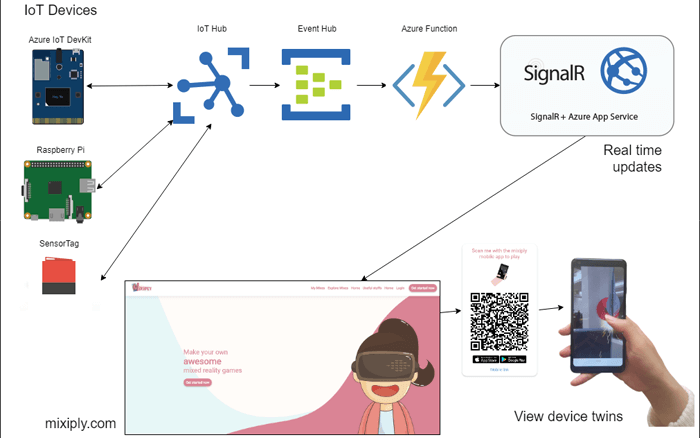
Now it’s time to put all our previous work together to make an end-to-end AR digital twin prototype. Mainly, we will be incorporating Mixiply into what we have done previously. Of course, a digital twin does not have to be visualised in AR, but we thought it would be a good way to demonstrate the ease of AR development in Mixiply, as well as being a cool way to show a digital twin. The prototype architecture will look something like this:
What is Mixiply?
Mixiply is a platform for creating and sharing AR/VR games and apps, a product of Theta’s Innovation Lab, developed in collaboration with Newland Intermediate’s MiniDevs. Mixiply makes AR accessible with a simple programming interface, allowing you to create an immersive AR environment. Mixiply supports the handling of images, 3D models, sounds and more, on any AR-capable device. Currently Mixiply is available on the Web, App Store and Google Play.
Getting started with Mixiply
To get started on working in Mixiply, we created an account and first explored the already available experiences, also known as Mixes, in the ‘Explore Mixes’ tab. There you can find Mixes made by members of Theta, the public and the MiniDevs, which you can choose to remix, or run. Other than remixing, you can also start a mix with ‘Create new Mix’ found under ‘My Mixes’, which is where all your remixes and original mixes live.
To help you with writing your own scripts, you can use the documentation available, found under the home page. And there’s an ‘Uploads’ section where you can add files to use in your mixes to make them more dynamic; uploading a file creates a unique file path to be used in your Mix.
Once you are within a new Mix, you can start adding to your script in the ‘Code’ section. All Mixes must be written in JavaScript and are built upon three main functions: setup, start and update. You can find the start-up syntax under ‘Global’ in the documentation or remix ‘First Mix’ in ‘Tutorials’.
Debugging can be done with any AR-capable device, coupled with a QR code scanner; Mixiply’s Mobile App has a built-in scanner. To debug, just scan the Mix’s QR code in ‘Debugger’ and watch the web console return any logs or errors.
We made extensive use of ‘Upload’ to add 3D models to our mixes including devices and telemetry 3D models. 3D models must be added following the ‘Asset’ syntax found in the documentation; you can fetch the asset’s URL under ‘Uploads’. We’ve created our 3D models in Maya and Tinkercad, transforming them to match Mixiply’s 3D model file types, .gltf and .glb.
Sending our sensor data to Mixiply
We need to re-direct where our sensor data is going. We will be pointing it to Mixiply’s in-built SignalR hub. This has been built into the Mixiply backend as an experimental pre-release feature which we hope will be generally available soon. If you are interested in using this feature of Mixiply, please contact us.
To forward our incoming IoT Hub messages to the Mixiply Hub, we need to modify the Azure Function we created previously. The Run method in the function now looks something like this:
We invoke two different methods on the SignalR Hub; Join and SendDataToOthers. Each method takes the Mix id and Group id, which we are now sending in our device message payload. The Join method takes advantage of SignalR’s ability to let you create different client groups. Clients can ‘subscribe’ to a group so that they can publish and receive data for that specific group.
Once our function has been redeployed, it will now be passing all the IoT Hub incoming messages to Mixiply, making our data available for us to do some 3D modelling with!
Modelling a digital twin in Mixiply
1. General Setup
Here’s how we created the script for modelling a digital twin of a Simulated Device in Mixiply.
First, we defined several global variables so they’d be reachable by all devices.
The various telemetry values can be set at your own discretion, depending on the device you are planning to model. We initialized a dictionary of “devices” to hold our various device objects and set the initial state of ‘isConnected’ to ‘false’. We also declared the variables ‘liveData’ and ‘groupName’, essential for connecting to a live data stream (i.e. to the Mixiply SignalR hub).
In the ‘start’ function, we defined an arbitrary ‘groupName’, which will be used to join a LiveData group.
‘LiveData.connect()’ will create a connection to the LiveData group once it’s supplied a ‘groupName’; this is done in the update function.
In the update function, if LiveData is connected and ‘isConnected’ is false, join a LiveData group with ‘groupName’ 1234 and set ‘isConnected’ to true.
2. On Data Received
Now that a connection to a LiveData group is created, we can process received data with the onReceiveData function. A callback is invoked for each new received message.
The invoked onReceiveData callback is decoupled naturally into two parameters, ‘groupName’ and ‘data’. ‘groupName’ is defined in start and ‘data’ is received from the Simulated Device.
Individual pieces of data received from the Simulated device can be retrieved using the data dot notation.
For example, say your data looked like this, then you can retrieve the device name using data.device
We query the ‘devices’ dictionary about whether it has seen this device before using its unique identifier or name. If this device doesn’t exist in ‘devices’, we create a new dictionary object, assigning each key a value from the ‘data’ parameter. We used ‘parent’ to limit each device to a location and use getPropertyCount to approximate how far away from the previously added device we should set the new device.
getPropertyCount is a helper function that returns the current count of existing devices within our ‘devices’ dictionary in order for us to space out the devices within the environment.
We then use a switch to catch the type of device we are handling, which invokes each device’s own handling function. We have a handling function for each device. receiveSimulatedData handles our Simulated Device’s data.
3. Telemetry Data Modelling
We check for the existence of each telemetry value in the new message and set them to default values if they don’t exist. We do extra checks for humidity to make sure they lie between our predefined defined min and max.
We created a getRotation helper function which returns the rotation associated with each data.orientation value. We have mapped a rotation for each orientation value, dependent on the modelling of our device.
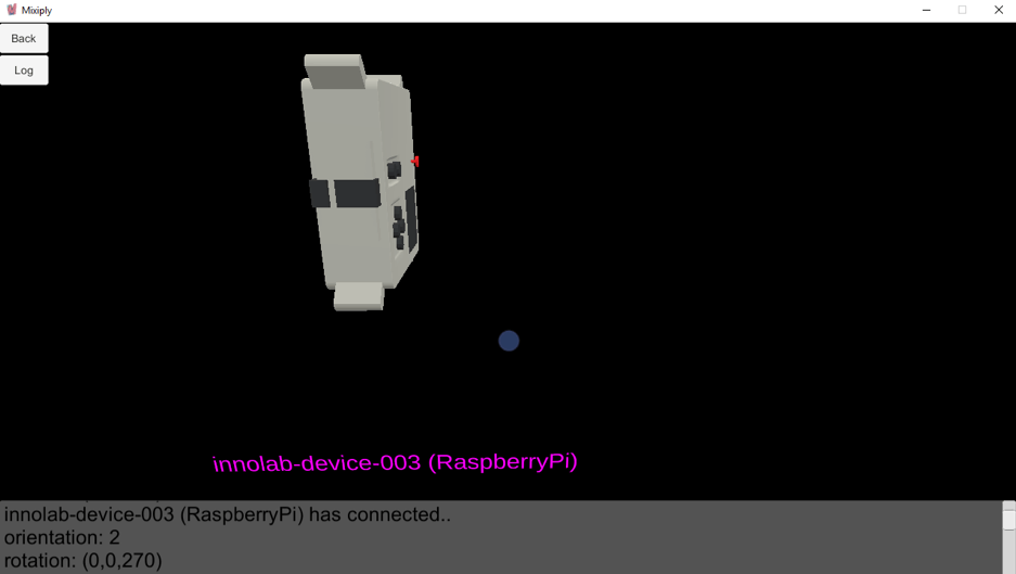
For example, we set an upright device to have an orientation of 2. The rotation of the model to be shown in Mixiply is obtained by passing the orientation value to a function called getRotation. In the image below, we are viewing a model of the Raspberry Pi in the Mixiply desktop app. You can see that the model is in orientation 2, which is defined with a rotation vector of (0, 0, 270). This means that the model has been rotated around the z axis by 270 degrees.
We created a getOrCreateMixiplyObject function to test if the object used to model a particular telemetry value has already been created. The modelling object can be any primitive type or an uploaded asset from the setup function. Notice that the object we’ve used for the rotation and temperature telemetry is a ‘Primitive.cube()’ and for humidity, we used a rain ‘drop’ asset.
If the device modelling object doesn’t exist, then create it and assign it to the device object within ‘devices’. Note that the objectFactory parameter is a function which sets the location and scale of each modelling object relative to the ‘parent’ using the keyword ‘Local’. If the modelling object already exists or if it was just created, return the modelling object. The modelling object is to be transformed once returned, according to each newly received live data message.
getOrCreateMixiplyObject is called for each new telemetry value received and then a specific modelling object transformation is achieved using helper functions like getRotation.
We have a text label assigned to each modelling object, which is assigned a colour between magenta and cyan depending on the value of ‘Math.random()’ using the ‘lerp’ method. The label is set below each modelling object, discovered using the ‘parent’ position.
We use the same ’lerp’ method to assign temperature’s modelling object a colour between blue and red, red being hot and blue being cool.
We’ve used a primitive cube to demonstrate temperature changes experienced by an IoT Device, watch as the cube turn red as it becomes hot and blue as it becomes cold.
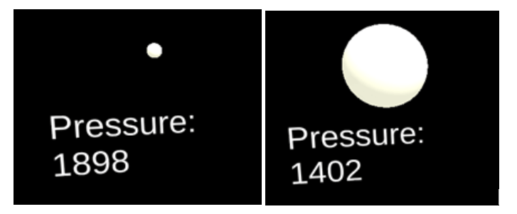
We set pressure’s modelling object of ‘Primitive.sphere()’ to a certain size depending on the pressure. The larger the pressure, the smaller the object. getSize returns a vector we use to set the size of the sphere with ‘setLocalScale’.
We also set humidity’s modelling object of asset ‘drop’ to a certain transparency depending on the humidity. The greater the humidity, the more opaque the 3D raindrop object. ‘sheer’ returns the input ‘humidity’ as a value between 0 and 1, ‘out_min’ and ‘out_max’, respectively. This is because the opaque value of setColor, defined as alpha and which we’ve called ‘sheer’, only accepts values between 0 and 1. getRainTransparency also expects predefined min and max humidity, ‘h_min’ and ‘h_max’, respectively.

With receiveSimulatedData fully defined, you can start sending telemetry data from the live data hub to reflect changes in the modelling objects of the mix. You can also model more than one device at a time, so long as you follow the procedures above. To handle another device, be sure to add an additional switch case to onReceiveData, create a new receive‘Devicetype’Data function to be invoked by switch. Also create helper functions to pair with your new receive’Devicetype’Data function to achieve the modelling object transformations you wish to see. You could choose not to define any new helper functions if you find that the ones used by receiveSimulatedData are just what you need.
Creating and using Digital Twins
We incorporated Azure IoT Hub, Azure Functions, SignalR, and Mixiply to show IoT devices in AR, visualising their sensory data in real time. We showed how data like temperature, pressure and humidity from real world sensors could be visualised as a digital twin in augmented reality in real time. While it’s been exciting to work with a range of cloud services, real time web apps and AR all in one prototype, how is this more broadly relevant?
In lots of ways, in fact. The business value of digital twins comes down to the fundamental idea that a digital twin represents a collection of data from a physical object. This makes digital twinning a powerful concept because it enables monitoring in a remote way. Businesses can optimize operations, systems and manufacturing processes, as well as keep track of their maintenance needs without having to physically be on site. Simulations using digital twins can be used for staff training, product design, or incident scenarios. With the help of AI and machine learning, the data collected could also be used to predict and diagnose problems before they even happen.
Digital twins are becoming more ubiquitous in all forms of IoT, and soon you can expect them to be prevalent in all sorts of businesses. There are many existing real-world digital twin applications, and equally many more that have yet to be imagined.
We hope this series of blog posts has got your imagination going with ways to incorporate digital twinning into your own projects.
Find out more...
Take a look at our interview with iStart: Are digital twins coming of age?
Related Posts
.png)
July 1, 2019
Exploring digital twins part 1: Azure DevKit and IoT Hub
This is the first in a series of tech blog posts about some recent Innovation Lab work on Internet of Things (IoT), digital twinning, and the 3D visualisation of IoT device sensor data in Mixiply, Theta’s augmented reality (AR) platform.
%20(1).png)
July 8, 2019
Exploring digital twins part 2: IoT Hub, Azure Functions and SignalR
This is the second in a series of tech blog posts by Rose McColl and Lillian Ho, about some recent Innovation Lab work on Internet of Things (IoT), digital twinning, and the 3D visualisation of IoT device sensor data in Mixiply, Theta’s augmented reality (AR) platform.
%20(1).png)
July 15, 2019
Exploring digital twins Part 3: Raspberry Pi and Azure IoT Hub connection using Python
This is part three in a series of blog posts about some recent Innovation Lab work on Internet of Things (IoT), digital twinning, and the 3D visualisation of IoT device sensor data in Mixiply, Theta’s augmented reality (AR) platform. Extending from part one, this post will demonstrate sending telemetry from a Raspberry Pi IoT device to Azure’s IoT Hub, using Python.